Robot-Assisted Construction of
Fibrous Materials
This project is a continuation aimed to improve the Standard Bots RO1 cobot's capabilities in creating physical fiber matrices that replicate the collagen structure in the back of the eye. The objective of this semester was to collaborate with the UPMC Laboratory of Ocular Biomechanics to develop a robotic system for laying down and weaving fibers into a 3D matrix pattern. The system should be able to not only create a weaved string pattern but also should introduce autonomous operation capabilities to the robot tooltip.
Previous teams end effector
The previous senior design team created the idea for the gear train used in the current end effector, but their design has several drawbacks that prevented it from operating effectively. Most importantly there was too much friction in the gear train, this resulted in the stepper motor not being able to drive the geartrain consistently, and overheating quickly. Additionally the spool was quite small with a sub optimal fiber capacity.

Basic Design
The core idea of the end effector is to contain the fiber on a spool that allows it to be dispensed reliably. While at the same time including something that can weave the dispensed fiber around an existing structure. This is the key reason the professor was interested in our team creating a new solution, because although there were several existing solutions for robots that could wind fibers around a structure of pins, there was no available solution for something that could both wind fibers, and weave them around themselves.
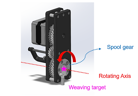
Casing design
The design of the front and back casing plates prioritized easy disassembly and internal part access, this was helpful when quickly ideating and changing out damaged parts. Another innovation was to support the interrupted spool gear from the inside. Because the lower gear has a large gap in it, it is impossible to support it with a standard bearing. Instead some sort of custom bushing must be used. The goal then becomes to reduce the surface area of the bushing contact zone as much as possible to minimize friction. I chose to support the gear from the outside as opposed the previous teams decision to support the gear from the inside. This allowed me to support the gear with two 45 degree conical surfaces. This greatly reduced the surface area from the previous design, helping with gear train efficiency. It also opened up the inside of the gear for features, simplifying the design

Robot attachment method and location
The way the end effector was attached to the robot took into consideration how it would be removed and replaced when on the end of the arm. The exact locations of the screw holes in the mounting block were calculated so that when mounted to the end effector plate, the fiber extrusion tube was colinear with the final axis of the robot, simplifying robot control by allowing for the end effector to rotate in the plane parallel to the fiber matrix board without changing the position of the tube.

Gear train modifications
Although I used the same basic geartrain layout as the previous team, several changes were added to increase efficiency, and allow for long windows of use. Because the bottom gear is interrupted, two idler gears are necessary to ensure that power can always be transmitted from the motor gear to the spool gear. This arrangement comes with the downside that the spool gear repeatedly disengages and re-engages the idler gears, if the idlers are slightly out of alignment or misshapen, then the geartrain can jam easily. This issue was very apparent with the previous iteration of the end effector, which would repeatedly bind under use, with no reliable way of preventing it. I theorized that if I replaced the spur gears with helical gears, I could greatly reduce the chances of the geartrain binding, because helical gear teeth engage gradually as opposed to the instantaneous engagement of spur gear teeth. This gives the gears space to properly align before the first tooth is fully engaged. This proved successful and the new geartrain has never jammed under use. I made the final gears "herringbone" gears, where the helical profile is mirrored. This cancels out the axial forces generated from the helical geometry, and also has the added benefit of locking the geartrain together axially, making gear mounting simpler.

Compliant spool tenioner
A topic of considerable discussion when planning what the new solution would look like was how much tension should be in the fiber when the matrix is being created. There must be enough tension to keep the fiber held in place on the pins after it is laid down, also, more tension will also prevent fibers from being pulled away once another fiber has been weaved around them. However, too much tension will put additional stress on the pins and the end effector. This could reduce the lifespan of these components or cause the pins to move out of alignment over time. The optimal tension could only be discovered experimentally, so a solution for quickly modifying the effective tension in the fiber was necessary. The tension in the fiber depends on the force it takes to rotate the spool, which itself depends on how much dynamic friction the spool faces experience. The black bracket seen below that mounts the spool was printed with a lower infill than the other structural components of the end effector. As the screw that serves as the axle of the end effector is tightened, it bends the spool bracket until the sides begin to touch the spool. Careful adjustment of the screw causes the sides to press in on the spool with more or less force. This directly controls the tension in the fiber. Using this feature, we were able to arrive at an optimal tension value.

Spool lock with servo
The final innovation from the previous team was the addition of a spool lock. In an effort to increase the level of automation of the final solution, we wanted something that would allow the robot to automatically lock the fiber to the matrix, so one could simply cut the extra fiber and have a complete and portable design. We achieved this with 3D printed pins with a slot cut in them for the fiber to be pulled into. In order to make sure the fiber would stay in the ending pin even with significant disturbance, they were designed to require a significant amount of force to pull the fiber into them. This amount of force was much greater than the optimal tension in the fiber under normal use. We decided the easiest way to overcome this challenge, was to add a small servo motor to the end effector that could lock the spool in place, preventing it from rotating. This allowed us to generate very large amounts of tension in the fiber by moving the robot arm small amounts. Ultimately resulting in use being able to consistently place the fiber into the pin to finish the fiber matrix


Final matrix being weaved
We successfully created a solution that could consistently wind fibers around pins and weave fiber around other fibers. This is demonstrated in the video below that shows a simple pattern of concentric circles being created, showcasing both the winding and the weaving. The pin locking is also shown at the end.
